
This tutorial is for anyone who wants to make a sleek, web-controlled lighting rig for their Prusa i3 3D printer. To begin, here is a list of hardware and materials that I used for the project:
• Raspberry Pi 3 - Model B (With a power supply)
• Silicone Cover Stranded-Core Wire 26AWG (Or any wire, really)
• 5V 2A Switching Power Supply w/ USB-A Connector (Or any 5V, ~2A USB power supply… I’m using one from Apple.)
Everything else you need will be 3D printed. Here is a list of files I used in this project:
• Raspberry Pi 3 MK3 Case (This one is specifically for MK3 and MK3S printers, but just about any Raspberry Pi enclosure will do.)
• Lighting Rig (This should fit any Prusa i3 frame, and the mounts can be redesigned to fit any printer with a frame.)
Tools needed for the project:
• Soldering iron & solder, wire cutters, etc.
Now that you have everything you'll need, let's get those lights working!
First thing we need to do is cut 4 strips of LEDs to length. For the strip I'm using, I was able to cut them down to 13 LEDs/segment, which is about 216mm long. I then soldered the 4 segments in series. IMPORTANT: make sure you're soldering the correct points to each other! I printed out a diagram of the model in Fusion 360 so that I'd know exactly how long to cut the connecting wires. Here is a PDF that you can print and solder/cut wires on top of. Make sure you leave enough wire at the end for it to stick out of the lighting rig, especially depending on where your Raspberry Pi will be.. Remember you can always cut it down later!
For the next step, we're going to wire the lights to the Raspberry Pi and test them. This is really important to do before you embed the lights in a print, in case you received faulty LEDs! For the next few steps I'm going to suggest you follow the tutorials that I link to, though I'll add a few comments about the places I got lost/needed a little more help. I was a beginner when I started this project and had zero experience with programming a Raspberry Pi.
I wired up my lights using this wiring guide... the power source being the USB plug. I recommend using jumper wires before you do any semi-permanent soldering to your Pi.
To get your Raspberry Pi ready, you'll first want to install OctoPrint if you haven't already. Here is a guide on how to do that. It will help you get it completely running and ready to go. You'll also learn how to use SSH which will be important for the remaining steps. I used an iMac to set everything up, so Terminal is how I connected to the Pi.
Next comes the fun stuff... installing the necessary software to use the LEDs directly from the Pi! Adafruit has a FANTASTIC guide on how to do this, it can be found here. Please follow their instructions in their entirety, but I'm going to quickly point out the important stuff.
1. Via SSH, type in the following command:
sudo pip3 install rpi_ws281x adafruit-circuitpython-neopixel
2. Next, they say "To demonstrate the usage of this library with NeoPixel LEDs, we'll use the Python REPL." If you're a beginner like me though, you won't know what to do here. So I found this great link after a little digging! Here's what you want to do... type sudo nano test.py to open up a text editing program built into the Pi. We're going to paste in the following text to turn the LEDs red (where 18 is the PIN number, and 52 is the number of LEDs):
import board
import neopixel
pixels = neopixel.NeoPixel(board.D18, 52)
pixels.fill((255, 0, 0))
import neopixel
pixels = neopixel.NeoPixel(board.D18, 52)
pixels.fill((255, 0, 0))
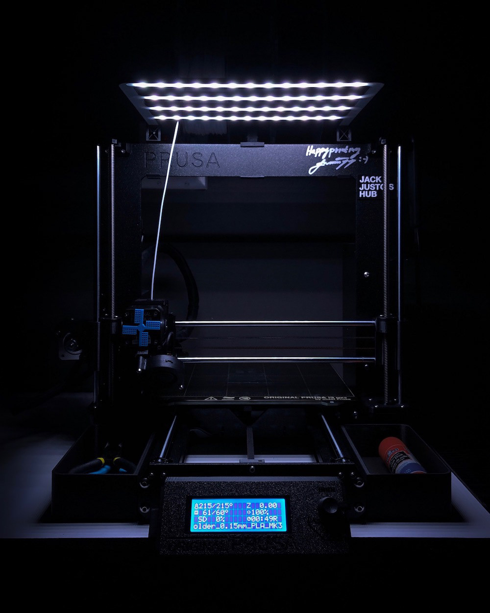
Then hit command + X to save, and hit enter. You've created the file and now you need to run it. All you have to do is type sudo python3 test.py which should hopefully turn all the LEDs in all four segments bright red! If that works, you can do another fun demo to test. Again, type sudo nano test.py and delete all the text in the file. This time, replace it with the "Full Example Code" on the Adafruit guide. Run it again using sudo python3 test.py and you should see the LEDs light up just like mine did in the GIF above.
Congrats! The lights are connected and now work. On to the OctoPrint plugins!
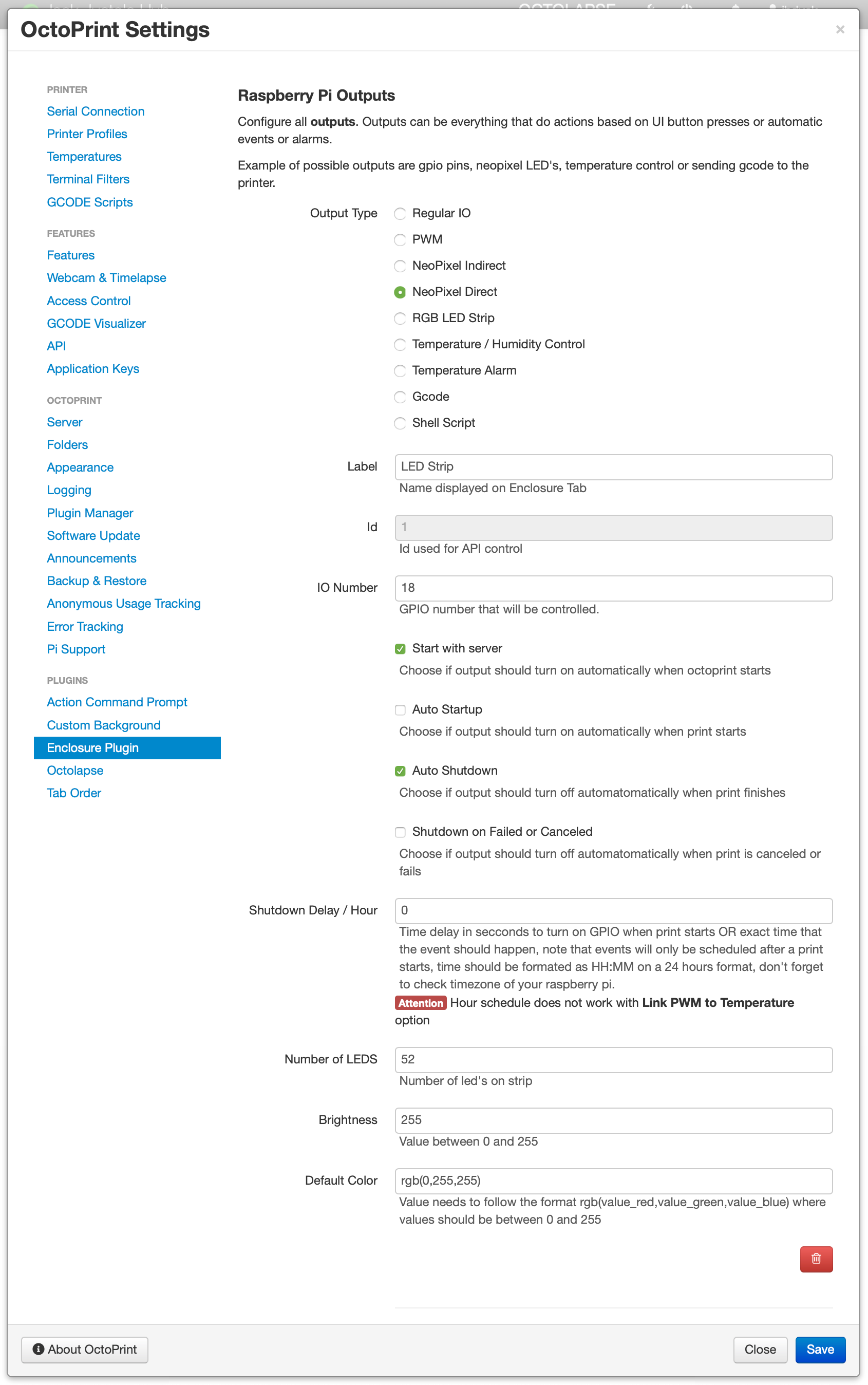
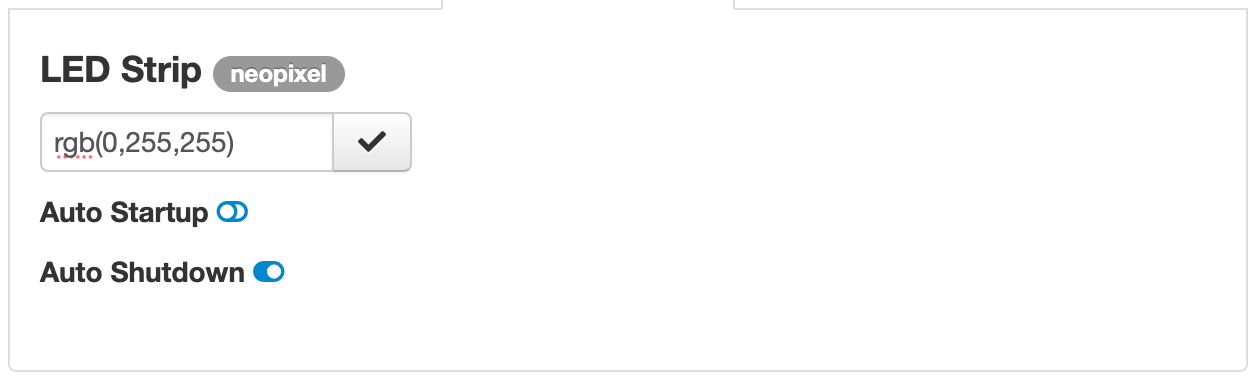
From the OctoPrint settings menu, install the plugin OctoPrint-Enclosure. Once that has installed and you Pi has rebooted, add the following information (see image above) to the plugin's settings. Feel free to play around with the settings to your preference. Hit save and your lights should work! You'll see a new tab in OctoPrint, and you should see your new output there. Click the text box to open a colour picker. Select a colour, hit the checkmark, and BAM! Light!
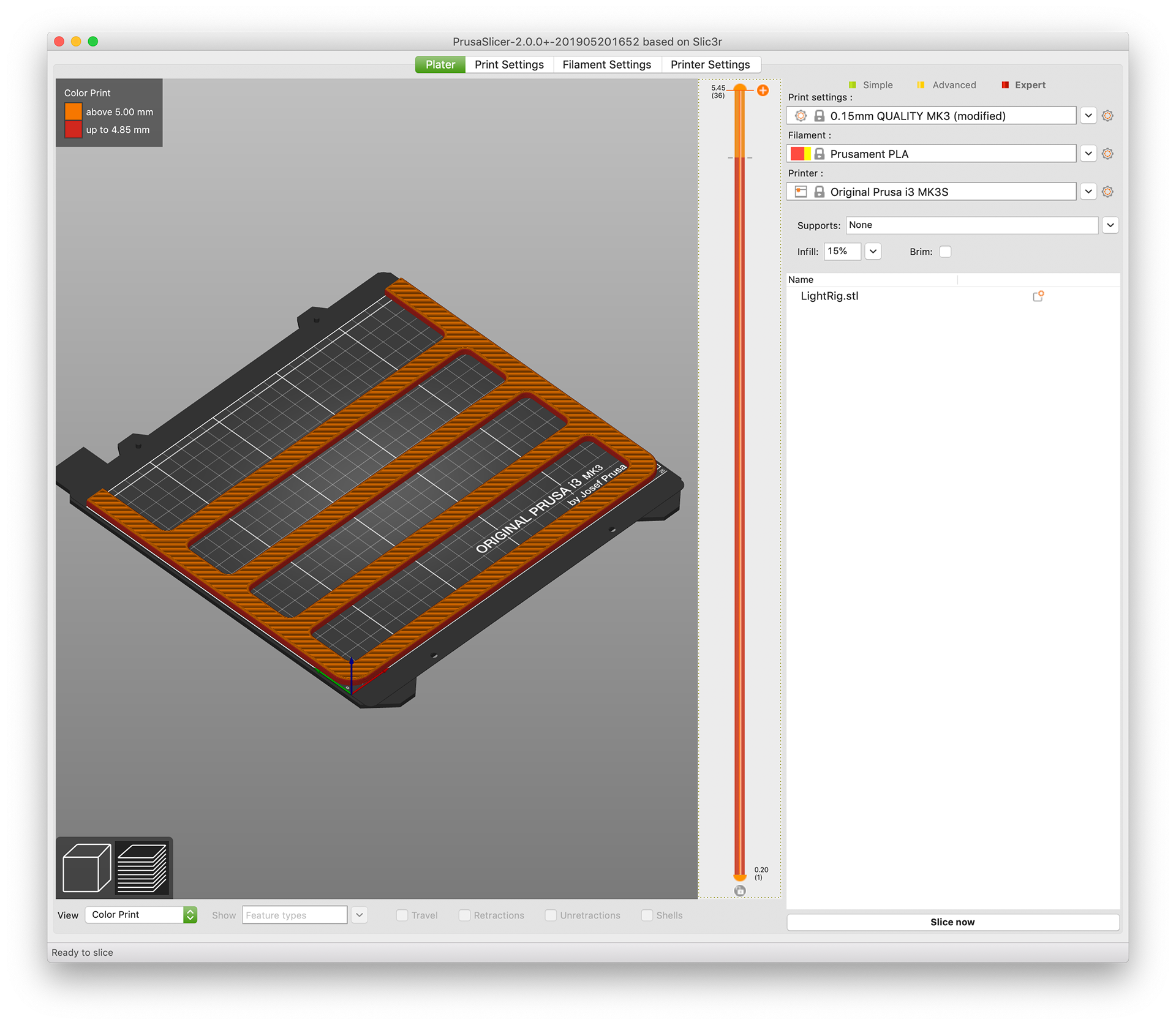
Now for printing... it's a lot easier than you may think. Prepare and slice the file for the lighting rig (link at the top of the page), and add a colour change at the moment the internal cavities get covered up. This is where you're going to place the strips inside the body, and change the filament from black to white. If you're using PrusaSlicer 2.0, the functionality is built right in, but for everyone else you can use Prusa ColorPrint. I sliced at a layer height of 0.15mm which means my filament change was at 5.00mm (layer 33).
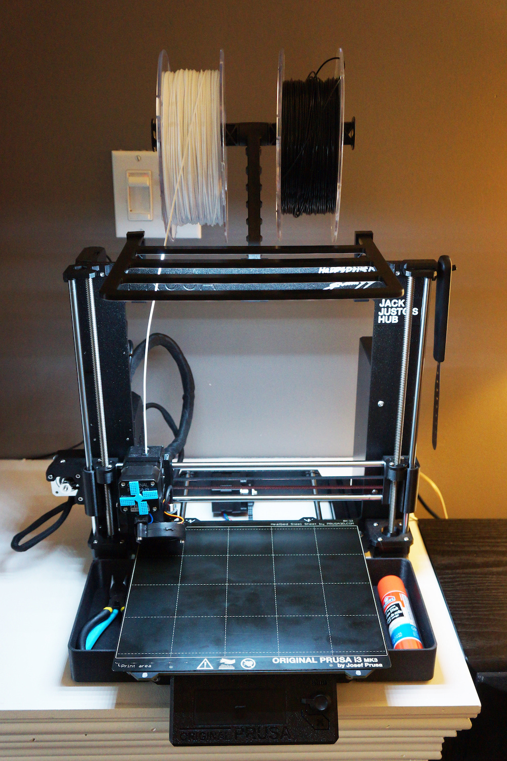
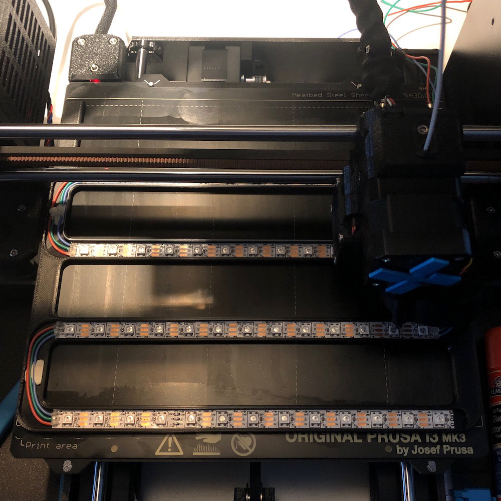
Place the strips in using a double-sided tape or adhesive (see image below). I also used sticky tack to ensure the wires would stay down while the extruder printed on top of them. Change the filament from black to white, and you're good to go! You can also use a different colour instead of black, but you may risk light leaking if the filament is semi-transparent.
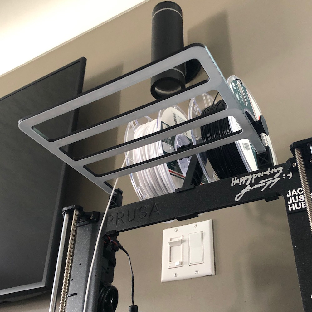
You just have to print the mounts as well and you're good to go!
Now just plug everything in (to the Pi, and connect your USB power for the lights), boot up your Pi, and turn those lights on in OctoPrint!